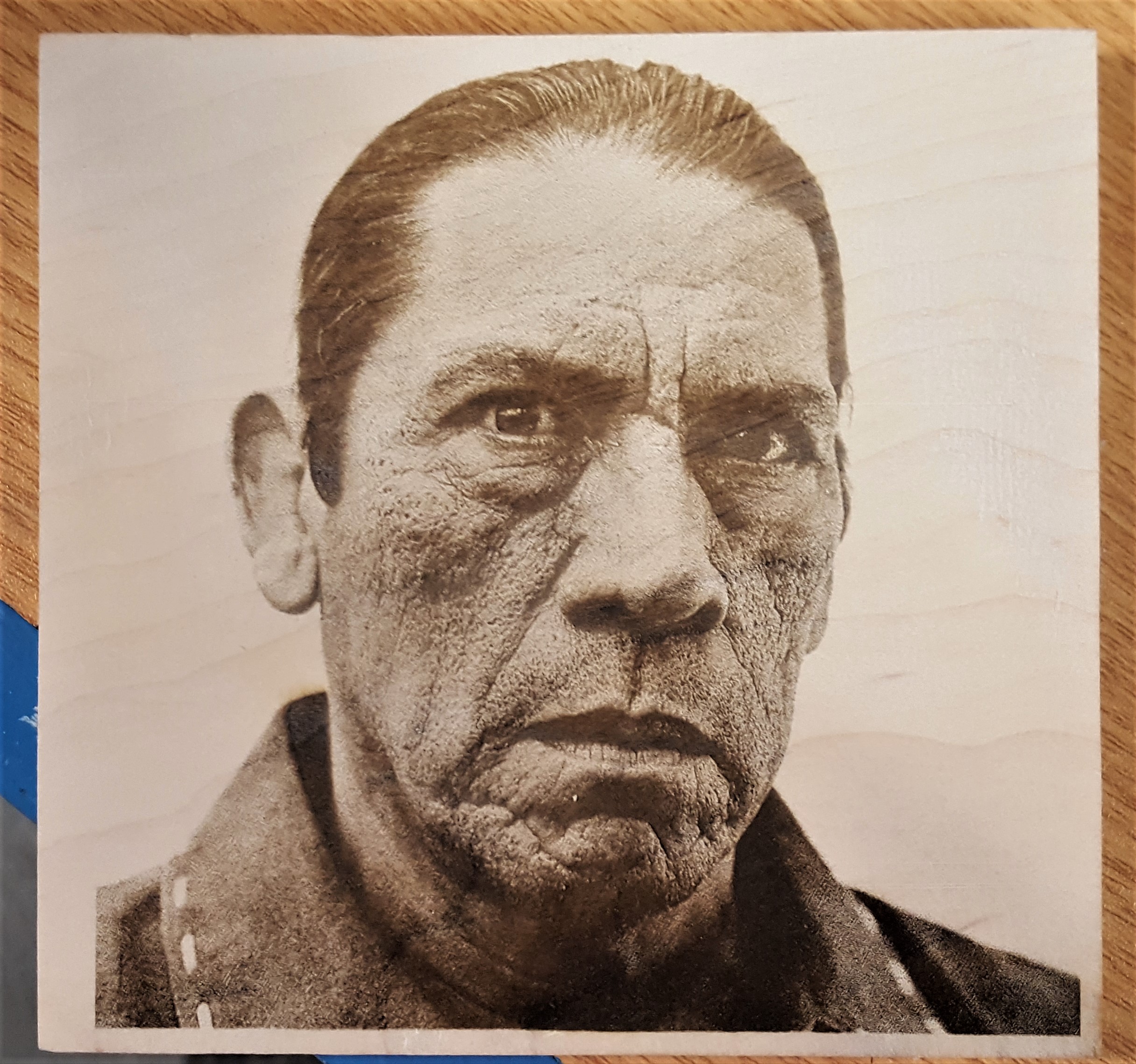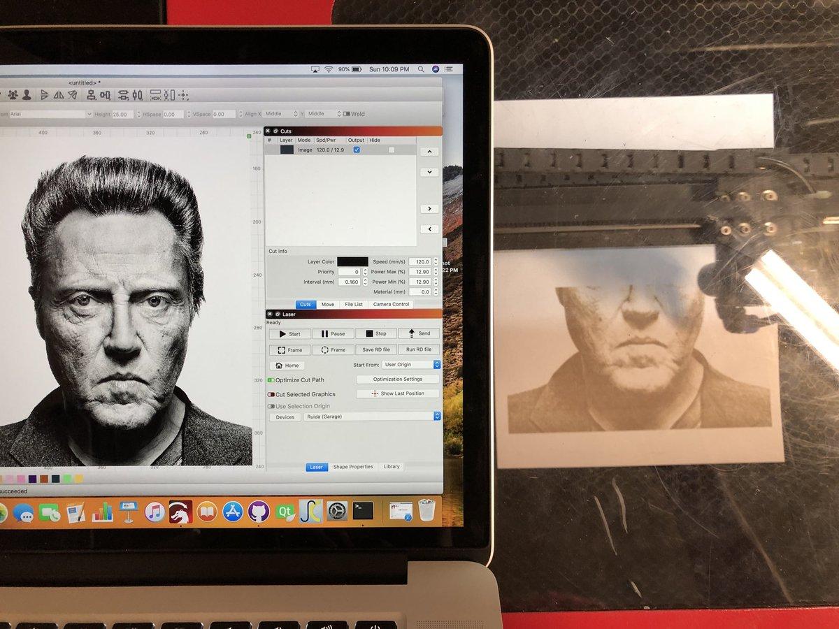

Wood for example requires a much wider scan gap than anodized aluminum. So dependng on the burn rate of the material, you may have to increase the scan gap to get the optimum resolution. This sound efficient but in reality negatively impacts the image resolution, tending to blur it.


As the centre spots get closer, as you can imagine, the effect can be quite a dramatic increase in power. When the scan gap is close, the edges overlap which doubles the power at that point on the material. When engraving an image made of dots, the resolution is maintained by definition between the "black" zones and the unburned "white" zones. It's similar to the pattern of a flashlight on the wall with an intense centre fading out to the edges. The burn microscopically varies from material to material. The laser spot on any material is not a crisp circle. There is another variable affected by Scan Gap, power.

If that seems simple, hold on to your hat. Like placing two pieces of screen material together at a slight angle. This avoids a moire which is interference which is resultant when two lined patterns are superimposed and are out of phase. When engraving photos, you want to use a scan frequency that is a multiple of the dot screen applied to the photo to convert it to a 2 bit. To convert it to distance between dots (passes) in mm you invert the number. For example 300dpi is 300/25.4 dp mm which equals 11.811 dpmm. Because I am used to resolution expressed as standard numbers DPI (dots per inch), I converted mine and keep a chart near my computer. I think the Rabbit laser software expresses the distance as a fraction of a millimeter, ie. The scan gap is the distance the laser moves vertically (the Y axis) between passes.


 0 kommentar(er)
